Manuscreen user documentation
You can read the manuscreen user documentation here, but you can also download it in a single pdf file to take it with you everywhere ! You can also find tutorials here !
You can read the manuscreen user documentation here, but you can also download it in a single pdf file to take it with you everywhere ! You can also find tutorials here !
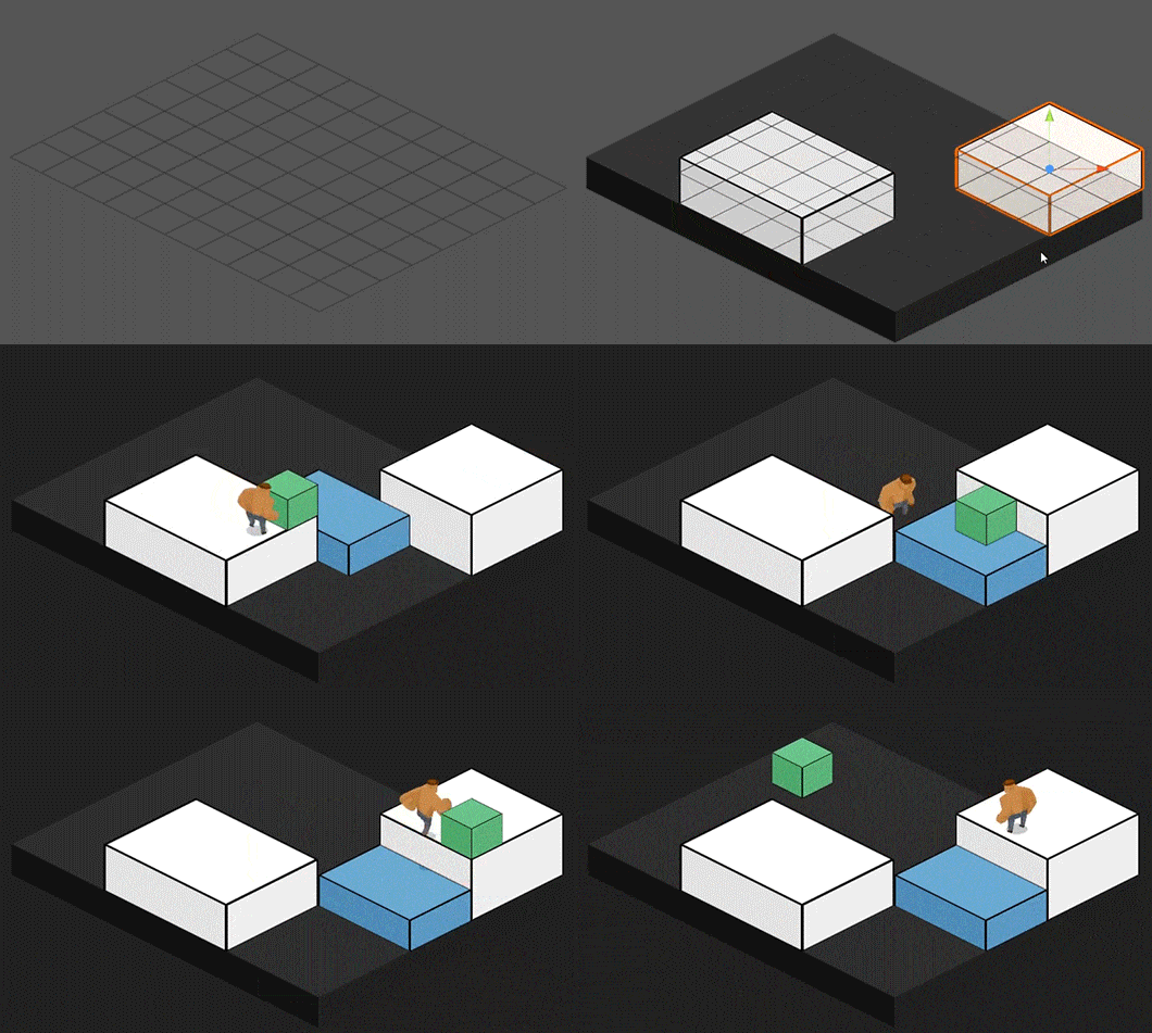
Our game, called “An Interesting Journey Of Mr Paf“, is born out of experiments with a 2D isometric concept. As 3D was not our artistic choice, the original idea was to try and manage a vertical axis in addition to the horizontal plane, in order to build bridges that the characters could both walk over and under. The result being more and more convincing as we progressed in our tests, we developed a GamePlay on top of this engine as we were creating it.
I was really surprised when I read Martin Pane’s article on making an isometric game. His approach of the problem is very interesting and also very different from mine because he doesn’t seem to use a TileMap concept, and thanks to that, the performances of his game might increase. My approach is much more conventional and inspired from many tutorials and examples I have found on the web. That is why, to echo Martin Pane’s reflections and also to help those who would like to try out 2D isometric, I decided to give an overview of my work to inspire other projects. Then it is up to you to choose the method best suited to your project, or even experiment yourself with a mix of both.
First of all, I want to make it clear that if you want to produce an isometric platformer, you should move towards a 3D rather than 2D approach for a start. You will dramatically reduce your development time using an orthographic camera, the physics and other powerful tools available on Unity, and the result will be much more optimized. However, if you can’t or don’t want to work in 3D — if you really don’t want to — the following content can help you.
The classical way to build a 2D isometric world is to use a TileMap. This principle allows you to simulate a 3D world view with a 2D coordinates system. You can find a lot of tutorials about what it is and how it works on the web. This concept is almost as old as video games. So I will not dwell much on this definition and all the theories that derive from it.
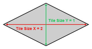
For our project, we chose to use tiles with a diamond form (to have an isometric view) with a 2:1 ratio:
Then we defined the origin and the axes of the isometric reference to stay consistent with what is commonly considered as 3D environment:
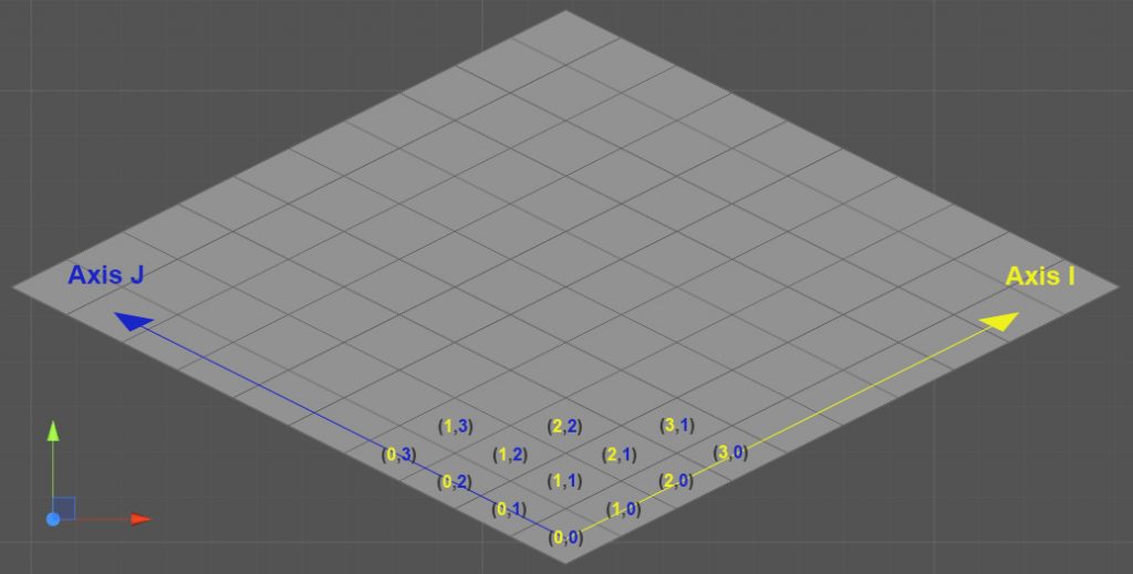
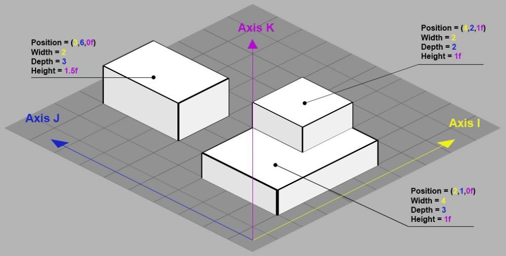
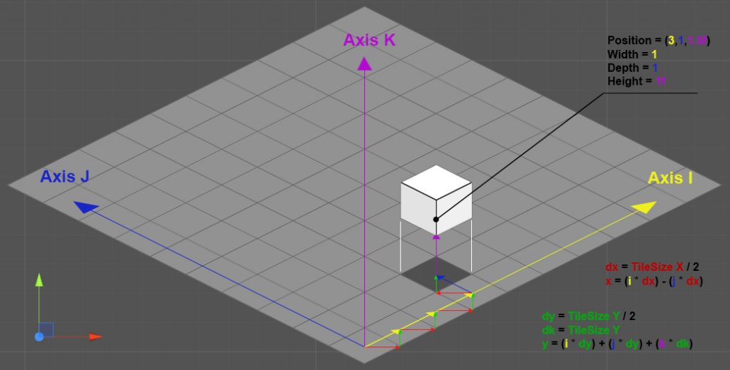
Then I added a vertical axe named K, defining its unit as the height of an isometric cube. 1K is therefore equal to the height of a tile. Unlike the I and J axes, that can only be defined by integers, the K-axis is floating, which will be needed to implement the gravity in the next phases of the project.
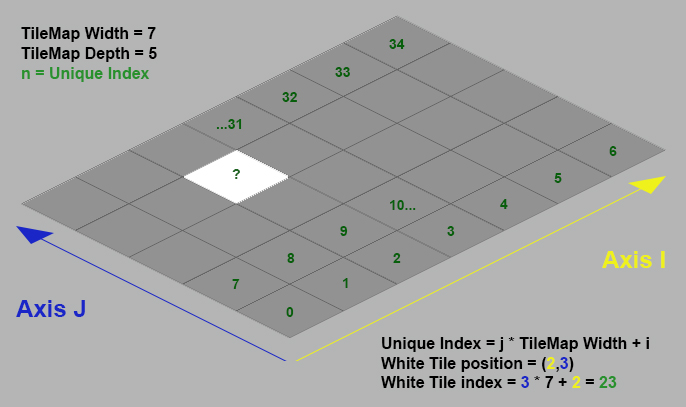
At the code level, you could be tempted to define a two dimensional array to reference the tiles. But a more optimal option consists in converting the isometric coordinates (i,j) to an integer index and then use a simple array. This conversion is based on the TileMap size:
To define and reference the isometric objects, I created a component representative of each logical object in the isometric reference, indicating its position on the [I,J,K] axes and size. I named it “Mapper”. Now you can place the mapper on the scene, depending on its isometric position:
Each mapper in the isometric world is referenced over one or more tiles depending on its size. However, instead of creating a list for each tile entity, I grouped them in a unique TileMap entity in order to increase the performance. It doesn’t contain a tile entities array, but an array of mappers reference lists. By doing that, the tile entity becomes a simple structure (and not a class! See here for more explenation) containing shortcut methods to the TileMap entity. Then the code becomes much faster and uses less memory.
Once the TileMap is operational, you can build your world. The sprite, which is the visual part of the logical object, is associated to the mapper with the SpriteRenderer component. I also made sure that it takes into account possible children GameObjects with SpriteRenderer, so that we could keep using more sprites for one mapper, and even particles systems.
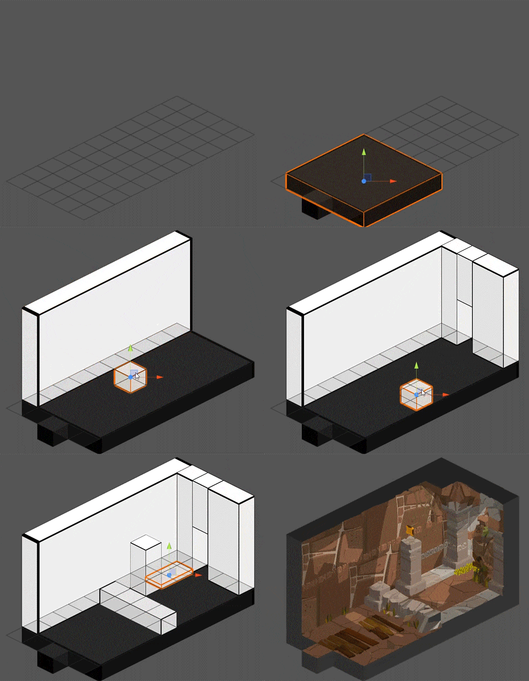
As for every game development, we needed a level editor because waiting for sprites to build levels is not a viable option. So I made a primitive entity that allowe building the levels and the game logic without the sprites.
In Unity, a sprite is nothing more than a 3D plane on which a material with a texture is applied. Like a 3D object, it is therefore defined by vertices, triangles and a UV mapping. You can easily verify this, by importing a sprite and putting it on the scene. Then change the “Draw Mode” to “Wireframe” and see the vertices of the sprite’s mesh.

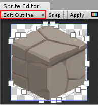
Note: It seems to be more efficient to add some vertices to cut a picture out instead of asking the GPU to process a lot of full transparent pixels. When you import a picture, Unity automatically cuts the transparency out and creates the vertices for you. Since the 5.6 version, the Sprite Editor contains an “Edit Outline” option that allows you to modify the vertices of your sprites. This option can be very useful.
A primitive is the representation of a cube, and you can change its size and colour. This cube contains 3 visible faces, Top, Left and Right. You could just use one mesh to draw those 3 faces, but I chose to divide it in 3 faces to be able to apply an outline and different colours on each side, and make the scene more readable.

See this post for more information about creating meshes from code.
To use the words of Martin Pane:
The priority order when rendering a sprite in Unity goes like this, from highest to lowest:
If two sprites share the same “Sorting Layer” and “Order in Layer”, the one closest to the camera (in 3D World coordinates) gets rendered first.
The isometric world is made of 2D sprites. It implies that you have to write an algorithm to determine the drawing order of all the sprites. If all the objects were static, it would be easy, but as there are characters moving in this world, things get more complicated.
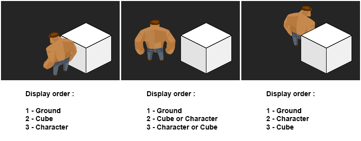
The sorting order is defined by the position and size of the objects on the TileMap. It is therefore possible to determine from the coordinates system of the isometric reference an exhaustive order of the objects. This order is then sent to the SpriteRenderers by the “OrderInLayer” property (from the code, this property is called « sortingOrder ») ranging from 0 (farthest) to N (nearest). The z position can be used to organize children and make animations inside an object with further renderers.
Note: Sorting properties (“sortingLayerId”, “sortingLayerName”, “sortingOrder”, etc) are not specific to the “SpriteRenderer” component but inherit from the “Renderer” component. You can access and modify them from code even for a “MeshRenderer” or a “ParticleSystem” component (see here).
Working in full 2D isometry can make you forget that you are not in a 3D environment and that some things are not possible. For instance:
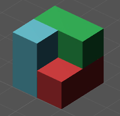
If you try to do that in 2D, you will have a problem: considering 1 sprite per cube, the blue one must be displayed in front of the green one, the green one must be displayed in front of the red one, the red one must be displayed in front of the blue one… You end up with what we called an “infinite triangle”, reminiscent of the Penrose triangle. “Infinite” because we got the following effect when executing the game:
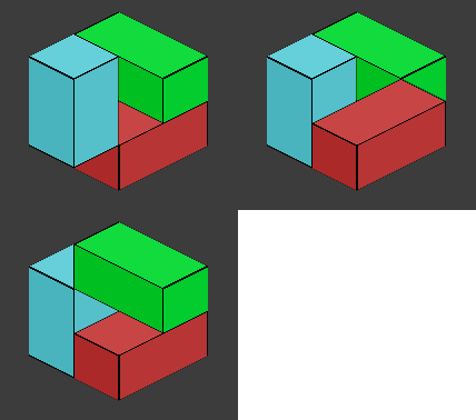
When building levels, it was easy to avoid them. But once the characters were moving, they could appear in unexpected places. After a while, we could anticipate most of the cases, but not all.
To determine the sorting order, I tried to write further algorithms minimizing the comparisons between the objects. Finally, the one that seemed to be the lowest performing turned out to be the only effective one. It consists of using a recursive method that determines the sorting order of an object after having determined those of the objects that are visually behind:
//The counter to increase
private int _currentSortingOrder = 0 ;

//Executed for each frame
private void Update(){

	//Get a list of all Mappers referenced on the Tilemap
	List<Mapper> mappers = Tilemap.GetAllMappers() ;

	//Initialize first all the mappers
	for(int m=0 ; m<mappers.Count ; m++)
	{
		//Initialize Method that set rendered property to false among other things
		mappers[m].InitializeRendering() ;
	}

	//Initialize counter
	this._currentSortingOrder = 0 ;

	//Then Render all mappers
	for(int m=0 ; m<mappers.Count ; m++)
	{
		this.RenderMapper(mappers[m]) ;
	}
}

private void RenderMapper(Mapper toRender)
{
	//Ignore if it is already rendered
	if(toRender.rendered) return ;

	//List Mappers Behind
	List<Mapper> mappersBehind = this.GetMappersBehindOf(toRender) ;
	for(int m=0 ; m<mappersBehind.Count ; m++)
	{
		RenderMapper(mappersBehind[m]) ;
	}

	//Apply sorting order and set rendered property to true
	toRender.RenderAt(this._currentSortingOrder) ;
	this._currentSortingOrder++ ;
}

private List<Mapper> GetMappersBehindOf(Mapper target)
{
	//Initialize the list
	List<Mapper> mappersBehind = new List<Mapper>() ;

	//List the mappers that are visually behind of target
	[...]

	//And return it
	return mappersBehind ;
}
he disadvantage of this approach method is that it has to be executed at each frame. That is why you have to optimize the code a lot so that it does not take too long to run (for example, do not use “foreach” loop for other things than an array, use a classic “for” loop if you can. Avoid to loop on dictionaries see here and here). If you want the game to run at 60 fps, each frame has to be calculated in less than 16 milliseconds. Considering the graphical rendering time and the fact that we were working with powerful computers, we defined a never-to-be-exceeded time of 10 milliseconds for this algorithm.
Moreover, the execution time increases depending on the number of objects, their size and the TileMap size. We got quickly limited for the TileMap size. For a 25 by 25 TileMap containing about fifty objects with a height from 1K to 7K, we got an execution time between 8 and 9 milliseconds. If the game is a succession of little rooms, it works fine. But we wanted to have a larger area where the player could move, like in a RPG. In order to do so, we have found a solution: the multi-TileMap.
Instead of having a 100 by 100 TileMap with an absurd sorting time of 50 milliseconds, we divided it into several little TileMaps of about 15 by 15. Each has a sorting time between 1 or 3 milliseconds. The trick consists in running the sorting algorithm only for the TleMaps visible on the camera, and adding a sorting algorithm for the visible ones.
The final result is not bad, and is executed even surprisingly with high-performance (I tested it on my ten years old laptop). But there will always be limitations, depending on how you build the level, especially as its height (K axis) extends and when you deal with physics and character’s motion across the map.
From this point, you can adapt the engine to a point and click game, a RPG, a platformer or whatever you want. Our game is a puzzle platformer, so I had to implement the physics on the vertical axis and the management of the horizontal movements. I will not double this article size explaining how it works, but I will leave you with some advice nonetheless:
